These days I am playing with the Olimex STM32-P152 board, trying to make it work and make it run some software. The STM32L152 on board has an embedded flash that can be programmed, so that when the chip is powered up the microcontroller will execute it right away, and I’m going to try that.
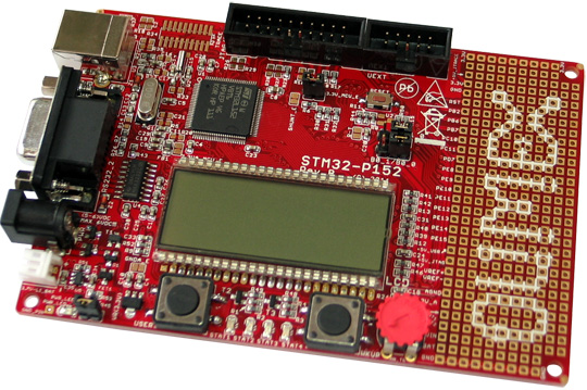
Olimex STM32-P152
The steps involved are:
- Requirements: Installation of needed software and hardware setup
- Development: writing and compiling a simple program
- Deployment: writing the program into the embedded flash
Requirements
The things I need to complete my objective are (apart from the Olimex board):
- A Linux (Debian in my case) PC,
- OpenOCD version >= 0.6.0,
- ARM toolchain: I use GCC ARM Embedded Toolchain
- A JTAG connection: I am using a C232HM-EDHSL-0,
The version of OpenOCD must be at least 0.6.0 because it’s the first version to support STM32L flash programming, older versions won’t work. In my case I have Debian testing where the packaged OpenOCD is version 0.5.0, so I had to install the package from Debian unstable (I used this method to install it), which is version 0.7.0. It’s also possible to compile and install OpenOCD >= 0.6.0 from source.
GCC ARM Embedded is a free toolchain that I find very useful, complete and easy to use for this kind of bare metal developing. I simply downloaded the Linux installation tarball from version 4.7-2013-q2, and extracted the content in “/opt” directory as root, with:
# cd /opt/
# tar xjf <download path>/gcc-arm-none-eabi-4_7-2013q2-20130614-linux.tar.bz2
The “readme.txt” file (in my case it was extracted in directory “/opt/gcc-arm-none-eabi-4_7-2013q2/share/doc/gcc-arm-none-eabi/“) contains the essential information to start developing with the toolchain. As written in the documentation, I appended the directory to the path, by adding at the end of “~/.bashrc” the lines:
PATH="/opt/gcc-arm-none-eabi-4_7-2013q2/bin/:${PATH}"
export PATH
About the JTAG connection, I’m using the same setup that I put in place in the post “JTAG connection with OpenOCD and FTDI cable“, so refer to that for hardware connection and how to change udev rules to allow normal users the access to C232HM.
Development
I wanted to run a simple program that makes a LED blink. The STM32-P152 board has many LEDs, and looking at the user manual the STAT3 and STAT4 LEDs are the simplest to use because they have just a resistor between the LED and 3.3V; in this configuration, I need to drive the signal to ground to turn on the LED, and to 3.3V (or to high impedance) to turn off the LED. I choose STAT4, that is connected to pin PE11 of the STM32L152, which means the Port E, I/O number 11. Using the reference manual and datasheet from the documentation page of the product, I wrote this “blink.c” file:
#include <stdint.h>

#define REG32(addr) (*(volatile uint32_t *)(addr))

#define GPIOE_BASE   0x40021000
#define GPIOE_MODER  REG32(GPIOE_BASE + 0x00)
#define GPIOE_OTYPER REG32(GPIOE_BASE + 0x04)
#define GPIOE_ODR    REG32(GPIOE_BASE + 0x14)

#define RCC_BASE 0x40023800
#define RCC_AHBENR REG32(RCC_BASE + 0x1C)
#define RCC_AHBENR_GPIOEEN 0x10

#define STAT4_PIN 11
#define STAT4_PIN_MASK (1UL<<STAT4_PIN)

static
void delay(int nops)
{
    while(nops > 0)
    {
        asm ("nop");
        nops--;
    }
}

static
void set_gpioe_moder(int pin, int mode)
{
    uint32_t moder;
    uint32_t moder_pin_pos;
    uint32_t moder_pin_mask;

    moder_pin_pos = pin*2; // 2 bits per pin
    moder_pin_mask = 0x3UL << moder_pin_pos;

    moder = GPIOE_MODER; // read from register
    moder &= ~moder_pin_mask; // clear moder pin field
    moder |= (mode << moder_pin_pos); // set moder pin field
    GPIOE_MODER = moder; // write to register
}

void main(void)
{
    RCC_AHBENR |= RCC_AHBENR_GPIOEEN; // enable GPIOE clock
    GPIOE_OTYPER |= STAT4_PIN_MASK; // open-drain
    set_gpioe_moder(STAT4_PIN, 1); // general purpose output
    while(1)
    {
        GPIOE_ODR |= STAT4_PIN_MASK; // output pin low -> LED ON
        delay(100000);
        GPIOE_ODR &= ~STAT4_PIN_MASK; // output pin high-z -> LED OFF
        delay(100000);
    }
}

void SystemInit(void)
{
    return;
}

void _exit(int code)
{
    while(1);
}
A couple of notes:
- I am using General Purpose Input/Output (GPIO) functionality to drive PE11.
- Before using GPIO registers, I need to enable the peripheral’s clock using the Reset and Clock Controller (RCC) registers.
- I configure PE11 as “open drain” so that when the pin is driven low the current passes through the LED into the pin, and when the pin is high it’s actually in high impedance and there’s no current flowing.
SystemInitand_exitfunctions are there because they are used in the GCC ARM toolchain startup code. If they don’t exist the linker complains about undefined references.
For bare metal programming, I also need startup code and linker scripts. These are conveniently prepared by the developers of the GCC ARM toolchain inside the samples directory. So I copied the “/opt/gcc-arm-none-eabi-4_7-2013q2/share/gcc-arm-none-eabi/samples/startup/startup_ARMCM3.S” and “/opt/gcc-arm-none-eabi-4_7-2013q2/share/gcc-arm-none-eabi/samples/ldscripts/sections.ld” files into the build directory, and created the following “stm32l152.ld” linker script for memory layout (taken from STM32L152 datasheet):
MEMORY
{
  FLASH (rx) : ORIGIN = 0x08000000, LENGTH = 0x00020000
  RAM  (rwx) : ORIGIN = 0x20000000, LENGTH = 0x00004000
}
I now have everything to build the program and generate a binary image to write in flash:
$ arm-none-eabi-gcc    -mthumb -mcpu=cortex-m3 -c -o blink.o blink.c
$ arm-none-eabi-gcc     -c -o startup_ARMCM3.o startup_ARMCM3.S
$ arm-none-eabi-gcc -Tstm32l152.ld -Tsections.ld -mthumb -mcpu=cortex-m3 blink.o startup_ARMCM3.o    -o blink
$ arm-none-eabi-objcopy -O binary blink blink.bin
The “-mthumb -mcpu=cortex-m3” options are taken from the toolchain “readme.txt“. The linker default behavior is to create a static executable, so the “-static” option is not necessary.
The final output of the build command is the “blink.bin” image that is ready to be be flashed into the chip.
Deployment
In order to write the flash, we need to connect to the board with OpenOCD and use its “flash write_image” command.
Since I’m using the C232HM FTDI cable, I use the “c232hm-edhsl-0.cfg” configuration file from last post. Then I need a configuration file for the STM32L152 chip, thankfully prepared by the Olimex developers on their website; I save the file as “stm32l.cfg“. Then I prepare another file, that I call “flash_blink.cfg“, containing the commands to run:
init
reset init
halt
flash write_image erase blink.bin 0x08000000
shutdown
The “reset init” command is needed to make the chip run at high speed, because when it powers up by default it uses its slow clock. The code that takes care of this is inside the “stm32l.cfg” file.
The Olimex STM32-P152 board comes pre-loaded with a demo software that blinks LEDs, uses the display and so on, but it doesn’t allow JTAG connection, probably because it uses the JTAG pins as other functionalities. The board has two jumpers that control the boot mode of the STM32L152, they are B0_1/B0_0 and B1_1/B1_0. If these jumpers are closed in B0_1 and B1_1 positions, the chip boots from SRAM, which contains random data at startup. When this happens, usually the chip stops immediately with an exception and the debugger is free to take control.
Be aware that the following procedure overwrites the content of the embedded flash. If you want to save the content of the flash you can do so using the OpenOCD command “dump_image“.
I configure the boot pin in SRAM boot mode, connect to the FTDI cable, power up the board and run the command to write in flash:
$ openocd -f c232hm-edhsl-0.cfg -f stm32l.cfg -f flash_blink.cfg
Open On-Chip Debugger 0.7.0 (2013-08-04-10:13)
Licensed under GNU GPL v2
For bug reports, read
	http://openocd.sourceforge.net/doc/doxygen/bugs.html
Info : only one transport option; autoselect 'jtag'
adapter speed: 1000 kHz
adapter speed: 100 kHz
adapter_nsrst_delay: 100
jtag_ntrst_delay: 100
Warn : target name is deprecated use: 'cortex_m'
DEPRECATED! use 'cortex_m' not 'cortex_m3'
cortex_m3 reset_config sysresetreq
Info : max TCK change to: 30000 kHz
Info : clock speed 100 kHz
Info : JTAG tap: stm32l.cpu tap/device found: 0x4ba00477 (mfg: 0x23b, part: 0xba00, ver: 0x4)
Info : JTAG tap: stm32l.bs tap/device found: 0x06416041 (mfg: 0x020, part: 0x6416, ver: 0x0)
Info : stm32l.cpu: hardware has 6 breakpoints, 4 watchpoints
Error: stm32l.cpu -- clearing lockup after double fault
Polling target stm32l.cpu failed, GDB will be halted. Polling again in 100ms
Polling target stm32l.cpu succeeded again
Info : JTAG tap: stm32l.cpu tap/device found: 0x4ba00477 (mfg: 0x23b, part: 0xba00, ver: 0x4)
Info : JTAG tap: stm32l.bs tap/device found: 0x06416041 (mfg: 0x020, part: 0x6416, ver: 0x0)
target state: halted
target halted due to debug-request, current mode: Thread
xPSR: 00000000 pc: 0x00010004 msp: 0xc842aeec
STM32L: Enabling HSI
adapter speed: 2000 kHz
auto erase enabled
STM32L flash size is 128kb, base address is 0x8000000
wrote 4096 bytes from file blink.bin in 0.513909s (7.783 KiB/s)
shutdown command invoked
The OpenOCD output contains the line “Error: stm32l.cpu -- clearing lockup after double fault“, and it’s precisely because when you boot from SRAM you can have unexpected behavior and the Cortex-M3 fires an exception. This procedure is not completely safe because the SRAM contains random data, and so it could contain something that by chance resembles code, but the probability of this happening is practically zero.
Then I change the boot jumpers to B0_0 B1_0 configuration (boot from flash) and reset the board, and the STAT4 LED starts blinking as a sign that the program is being run.
Conclusions
So the Olimex board is now loaded with a custom program that runs when the chip is powered on. We used just free software to do it and we did it at a very low level, without graphical environments, exploiting the functionalities of the ARM toolchain and OpenOCD.
The program is about 3KiB of size, which is a lot considering that it does practically nothing. The GCC ARM toolchain has the options to use a reduced libc (newlib nano) and it is also possible to exclude C++ support to reduce the C Run-Time beyond that.
In order to troubleshoot the procedure, the best way is to retrieve more information and analyse it, for example:
- Generate a map file adding “
-Xlinker -Map=blink.map” option to the linking phase, - Generate a disassembled list of the program with “
arm-none-eabi-objdump -S blink“, - Increase OpenOCD debug information with “
-d” option, - Connect to OpenOCD through “
telnet localhost 4444” and analyse the chip state with “mdw” and “dump_image” commands.
Next time I will use GDB to debug the program by attaching to OpenOCD built-in GDB server.
 Posts
Posts

September 15th, 2013 → 16:30
[…] playing with my Olimex STM32-P152 board: after connecting to its JTAG port with an FTDI cable and flashing it with OpenOCD, I wanted to debug a running program with […]
February 23rd, 2014 → 15:08
[…] Flashing the STM32-P152 board with OpenOCD […]
May 2nd, 2014 → 19:18
[…] my board. Here’s the “main.c” that I quickly wrote based on the blink example of this previous post (most of the information needed to write this code comes from ChibiOS docs, Olimex board […]
November 11th, 2014 → 23:15
[…] In conclusion, I found out that is pretty easy to use the new Nucleo boards (I assume the other boards are the same as mine) on Linux, with the exception of firmware upgrade . Next time I will try to write and compile some C program outside of mbed development environment and flash it on board, but I don’t foresee any problems since I already did something similar on an STM32 in a previous blog post. […]