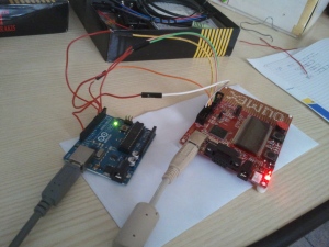
One of my personal project ideas is JTAGduino: using Arduino as a JTAG adapter. I wrote a couple of posts about it, and today I managed to connect it to a real target. All the code that I used here is present on my JTAGduino GitHub repository.
I have an Olimex STM32-P152 board, and I wanted to connect to its JTAG interface with my Arduino Uno. Warning: I had to be careful about the voltage of the signals: Arduino Uno has 5V I/O pins, while many other chips only support 3.3V. In my case the STM32L152 has 5V-tolerant pins, but according to the datasheet available in the product page the pins can sustain that voltage only if pull-up/pull-down resistors are disabled. Crossing the information from the user manual and the datasheet, the relevant I/O pins are: TMS: PA13, TCK: PA14, TDI: PA15, TDO: PB3. So it’s important (especially for prolonged use) to write in GPIOA_PUPDR and GPIOB_PUPDR the correspondent PUPDR fields to 0 in order to disable the resistors.
For the next step I wired the two boards together, connecting the 4 basic JTAG signals (TMS, TCK, TDI and TDO) and connecting the grounds together. The schematic of the Olimex board contains the information about where the signals are, while the pins to connect on the Arduino can be chosen according to the sketch you upload. In my sketch, I used pin 2 for TCK, pin 3 for TMS, pin 4 for TDI and pin 5 for TDO (array jtag_pin_map).
The Arduino sketch that I prepared allows to send JTAG sequences and receive the TDO readings through the default serial port; for example it’s possible to command JTAGduino from Python using pyserial. In order to see if the connection works I planned to read the device identification registers of the STM32L152. These registers are 32-bit codes that can be read from JTAG using particular sequences. The STM32L152 contains two TAP controllers, and each of them has one 32-bit code. The datasheet states that:
The TAP of the STM32L15xxx BSC (boundary scan) integrates a JTAG ID code equal to 0x06416041 0x4BA00477.
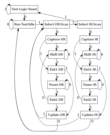
In order to read these values, one possibility hinted by IEEE 1149.1 specifications is to put the TAPs into Reset state and then scan out out the Data Register serially. This is done by exploiting the Finite State Machine in figure (figure that is also available in the doc directory of JTAGduino repository as a SVG Inkscape drawing or as a Graphviz dot file), that is common to all JTAG TAP controller that comply with IEEE. The state machine can be traversed using TMS values 0 and 1 that are sampled by the device at TCK rising edges. A good tutorial is available at fpga4fun.
To read two 32-bit ID codes, we can reach the Shift-DR state and then we shift out 64 bits from TDO. The implementation of a procedure to read the identifier codes is in read_idcodes.py script. The script can also detect the number of TAPs thanks to some rules of IEEE specs. Given that all ID codes are 32bit and that the least significant bit (the one shifted out first) is 1, we can shift into TDI the value 0, shift out 32bits and check if all 32bits are 0. If so, all the device identifier registers have been shifted out, otherwise we shift out other 32bits.
I ran the script from my Linux computer connected to Arduino through USB and it is able to detect the two TAPs and read the two 32-bit identification codes of the STM32L152. I suppose the same can be achieved in Windows by simply changing the name of the serial port.
From here, I can do something like adding to OpenOCD a driver for JTAGduino, so that I can debug the STM32L152 ARM Cortex-M3 core using the Arduino. I have to say that this experience made me more aware of the fact that a level shifter is needed to connect 5V logic to 3.3V targets. Also, some good JTAG cables and connectors would be preferable to those ugly wires.


 Posts
Posts
miguel angel Beltran
2016/08/23
excelente aporte D:
Ilan
2018/11/27
HI,
Do you try to set I/o of the ARM to high or low by python script?
Jerry
2020/12/16
hi ,
I have tried to read the IDcode of stm32f103 demo board with Arduino uno, but it’s not successful, could you share the program to me ,thank you very much!
email:42856240@qq.com
Jerry
2020/12/16
thank you very much!, I got the program
fhurzel
2021/11/30
Hi
Thank you very much for sharing your work. Definitely tempted to use it. what would you recommend using to shift the voltage from 5V to 3.3 V? I did not understand how to implement a level shifter.